| Intro: |
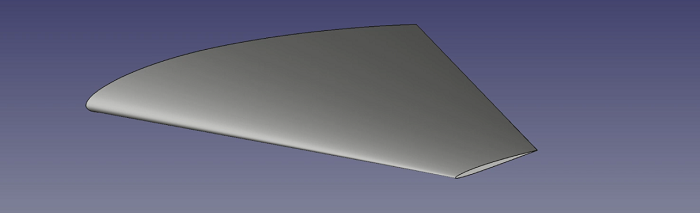
Here is the part that we will make. There are several ways to make
this shape in Freecad. This method uses a short macro to load the airfoil section
from a text file.
There is also a youtube video accompanying this description (embedded at
the end of this page).
The macro, airfoil section and a freecad file containing the
final shape are also available to download from the link in the footer.
I don't have comments enabled on this site, but if you have any comments or questions,
please feel free to leave them at my youTube channel after the video for this tutorial.
|
|
 |
| Freecad version: |
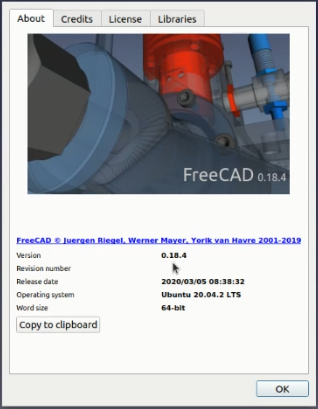
I'm using Freecad version 0.18.4 running on a fairly standard
Ubuntu 20.04 LTS. I've added curve and surface modules to Freecad but I don't
use them here so the standard Freecad 0.18.4 install should be ok.
|
|
 |
| Planform outline: |
The first thing I do is make a sketch of the planform. I don't
actually use the sketch to make the wing shape but I like to have it to guide me
during the process.
Create a new project, select Sketcher  ,
create a new sketch and then select the XY plane
as the working plane. Select the Create 2 Point Line tool ,
create a new sketch and then select the XY plane
as the working plane. Select the Create 2 Point Line tool  and make 4 disconnected lines roughly
in the shape of a wing as shown. It's not important if they're accurate as we constraint
them to the shape we want in the next steps.
and make 4 disconnected lines roughly
in the shape of a wing as shown. It's not important if they're accurate as we constraint
them to the shape we want in the next steps.
Freecad may automatically create horizontal and vertical constraints on the lines. If
they are not created, add horizontal constraints  for the top and bottom lines in the image.
Remove any vertical constraints.
for the top and bottom lines in the image.
Remove any vertical constraints.
|
 |
| Planform join lines: |
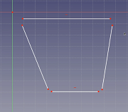
We constrain all the lines to be connected. Select the point constraint
 and then for each corner point, select the two points to connect in turn and they should
snap together.
and then for each corner point, select the two points to connect in turn and they should
snap together.
Do this for each of the corners. Then constrain the top left point to the origin in
the same way.
You should end up with a connected shape similar to the image but we still haven't
fully constrained the shape so yours might look different.
|
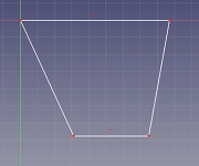 |
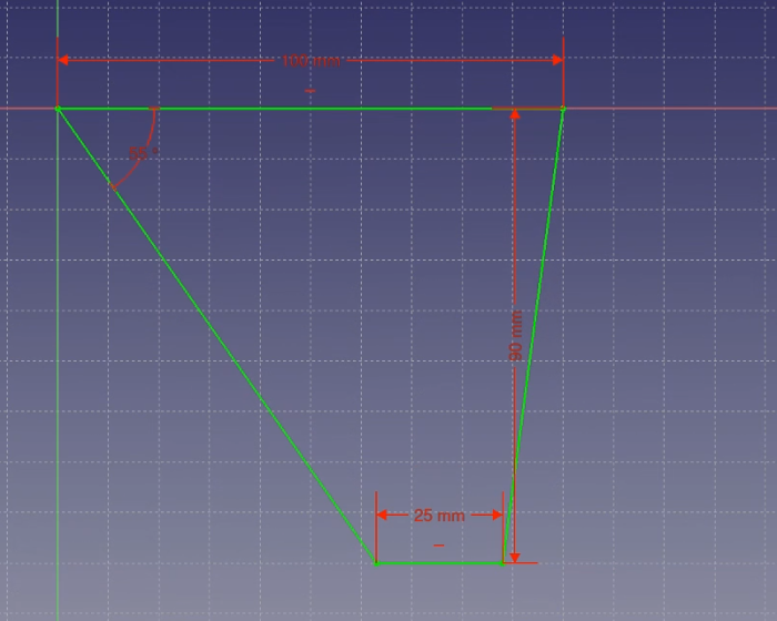
| Planform final constraints: |
Select the horizontal distance constraint  and then the top line.
This will be the wing root. Set the value to 100mm.
and then the top line.
This will be the wing root. Set the value to 100mm.
Repeat for the lower line, which will be the tip chord. We'll make a tapered wing
so set this to 25mm.
Next we'll set the leading edge sweep. The left line will be the leading edge so
select the angle constraint  and then the top line followed by the left line. The
angle we are setting is 90 minus the leading edge angle so for a leading edge sweep
of 35 degrees, set the angle to 55.
and then the top line followed by the left line. The
angle we are setting is 90 minus the leading edge angle so for a leading edge sweep
of 35 degrees, set the angle to 55.
Finally, we set the semi-span with a vertical distance constraint  on the right hand
line. Set this to 90mm. The lines will turn green, indicating the sketch is fully
constrained.
on the right hand
line. Set this to 90mm. The lines will turn green, indicating the sketch is fully
constrained.
|
|
 |
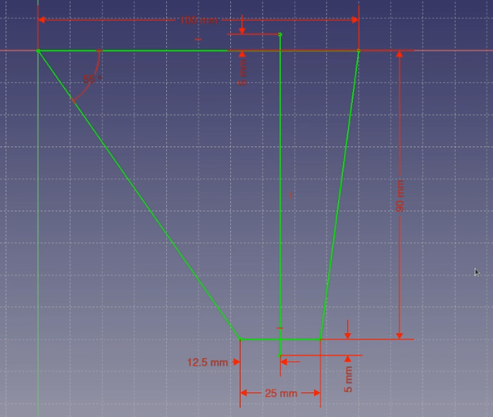
| Guide Line: |
I also add one more guideline to help me with the tip chord rotation
and positioning. Add one more line to the sketch, constrain it to a horizontal distance
12.5mm from the tip chord leading edge and then constrain each end with a vertical
distance of 5mm from the root and tip chord trailing edge points.
The final sketch should look as shown. Close the sketch  . .
|
|
 |
|
This is the end of part 1 of this tutorial. Continue to part 2 to complete the wing part.
There's also a video version of this tutorial below.
I don't have comments enabled on this site, but if you have any comments or questions,
feel free to leave them at my youTube channel
after the video for this tutorial.
|
|
|
|
