FreeCAD: Make a Smooth Wing Part from an Airfoil Section - Part 2
This article shows how to make a smooth wing part in Freecad from an airfoil section shape defined by coordinates in a file.
In part 1, we made a sketch of the planform we want. In part 2, we complete the 3D wing part.
Description
Intro:
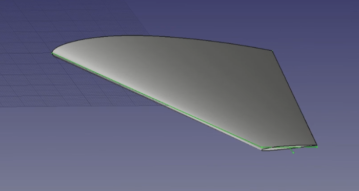
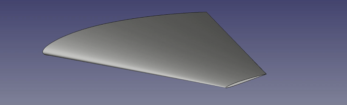
Here is the part that we will make.
There is also a youtube video accompanying this description (embedded at
the end of this page).
The macro, airfoil section and a freecad file containing the
final shape are also available to download from the link in the footer.
Please feel free to leave comments below or at my youTube channel after the video for this tutorial.
Airfoil:
Now we've completed a sketch of what we want, we can load in the airfoil section
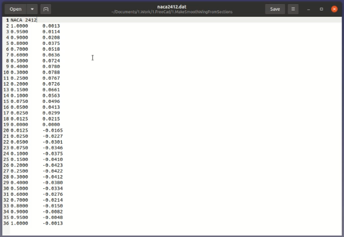
from a file using a short macro. I'm going to use a NACA2412 section. I downloaded this
from the UIUC Airfoil Data Site.
Download the airfoils in 'Selig' format for compatibility with the macro. The input file
contains x and y coordinates of the section with the x coordinates going from 0 to 1.
This section can be scaled to any size. There's one header line to remove before reading
in the data points. The file looks like this.
Macro:
Freecad uses python for scripting and I wrote the following short python
script for loading a set of x,y points and creating a BSpline. It can be used for any
2D shape.
# -*- coding: utf-8 -*-
# Loads points from a file and create a BSpline
# created by avianse.com
# License: LGPL v 2.1

import FreeCAD
import Part
import Draft
from math import *
import tkinter as tk
from tkinter.filedialog import askopenfilename

root = tk.Tk()
# show askopenfilename dialog without the tkinter window
root.withdraw()

# default is all file types
file_name = askopenfilename()

# Open the file and read the points
# This version expects 1 header/title line, then 2 points per line

points = []
with open(file_name) as f:
    # Remove the header line
    line1 = f.readline()
    # Read the data lines
    for line in f:
        xs, ys = line.split()
        xf=float(xs)
        yf=float(ys)
        # Save this point. I'm treating the points as x and z and setting y to 0
        points.append(FreeCAD.Vector(xf, 0.0, yf))

# Create a curve and then convert to BSpline
curve = Part.makePolygon(points)
Draft.makeBSpline(curve,closed=False,face=False)
If you know any modern software language, I think the code is fairly self-explanatory.
There are a couple of points worth mentioning. Firstly, I'm importing the section into the XZ plane
so I place the y coordinate from the file in the z slot
and make the y value 0.0 in points.append(FreeCAD.Vector(xf, 0.0, yf)).
Secondly, the section in Selig format is defined starting from the trailing edge, moving forward along
the upper surface to the leading edge, then back to the trailing edge along the lower surface.
If the two trailing edge points are identical, freecad will automatically close the curve
and you will not get a sharp trailing edge. For this section, the two points are not equal
so we'll get a gap at the trailing edge that we'll need to close.
If you want to override the Freecad behaviour you can hack the code in /usr/lib/Freecad/Mod/Draft.py
and comment
out the part that closes the curve when the first and last points are equal.
The part to comment out is in the makeBSpline
function. Comment the following lines from around line 970.
# Comment from here
    #if (pointslist[0] == pointslist[-1]):
.
.
.
    #return
    # should have sensible parms from here on
# to here
Import:
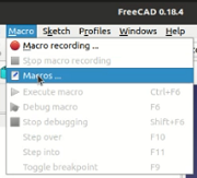
To import the section, make sure the macro file is placed in the correct
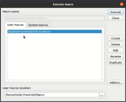
folder (usually Home/.FreeCAD/Macro on ubuntu) then select 'Macros' from the Macro menu. From the pop-up
menu, select the macro and hit 'Execute'.
A file dialog will open. Navigate to where you've stored the airfoil
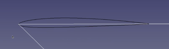
data file, select the file and press 'Open'. If all has gone well, the section will be
imported but may not be obvious because it is only 1mm long. Zoom into the root leading
edge and you should be able to see the section as shown.
Close Airfoil:
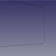
As this is currently an open section, we need to close the airfoil trailing
edge before making it into a single wire. Select the 'Draft' module, zoom right into the
trailing edge and carefully join the two trailing edge points with a 2 point line. Be
careful to select the end points as it is possible to select other points if you're not
careful. If you approach from 'downstream' it should snap to the end point.
Now you should have a BSpline and and Line in the Model tab on the left hand side.
Select both of these (Ctrl-click) then open the 'Draft' menu and select 'Upgrade'. This
should join the two lines and create a single wire.
Root Section:
We're going to use the wire we've made to make our root and tip sections,
starting with the root. First select the Draft module .
Now select the wire and make a clone .
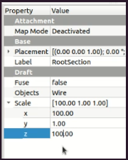
Right click the new wire in the Model tab and rename it to 'RootSection'.
With RootSection selected
in the Model tab, change the Scale property so that x and z scales are 100. This scales our
section up to the chord length we defined in our sketch. You may need to press the Refresh
button
to update to the new settings.
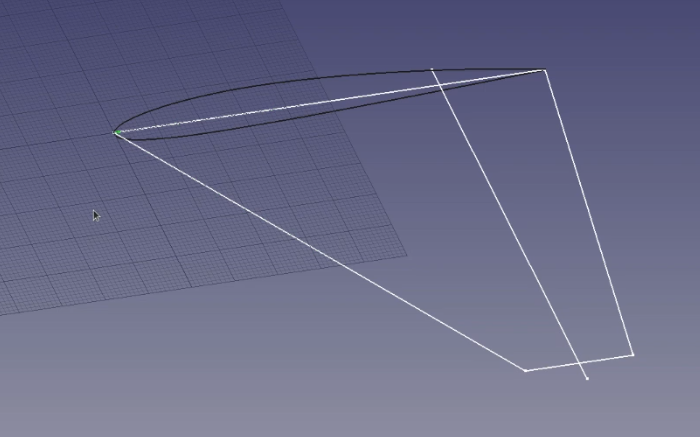
If you zoom out and unhide the sketch, you should see that the root section matches
the sketch.
Tip Section:
Now we're going to do something similar for the tip section.
Select the original section wire and in the Draft module make another clone. Right click
the new wire in the Model tab and rename it to 'TipSection'.
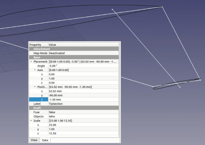
We're going to make a tapered and twisted wing, so there's a little more to do
with the tip section. With TipSection selected, set the x scale property to 25. This will
match the sketch and give us a taper ratio of 0.25. Set the z scale value to 12.5. This effectively reduces the
thickness to chord ratio of the section by 50% so the tip section will become a NACA2406.
Change the y Position property to -90 to match the semi-span from our sketch.
Knowing the leading edge sweep is 35 degrees, I
calculated the x Position needed to match the sketch is 63.02 (90*tan35), so I set that.
There's probably a way to directly link these sections to the sketch but here I'm
just using the sketch as a visual guide.
Finally, I want 5 degrees of 'washout' so I set the 'Axis' property to 0,1,0 (y axis)
and the Angle property to -5 degrees. This rotates the section about the leading edge
(the rotation is performed before the x,y shift),
so I shift the section down by setting the z Position property to -1.3. This lines it up
(by eye) with the guideline I made in the sketch earlier. The final tip section properties
are shown below.
Make Wing Part:
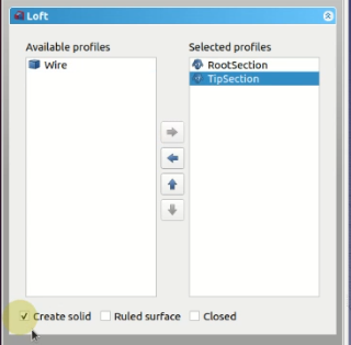
Now all that's left is to make the wing part. Change to the Part module
and select the loft tool .
In the task tab on the left, select the RootSection first and
add it to the Selected profiles. Next add the TipSection.
We're going to create a solid, so select 'Create solid' and then press ok. After a
short wait, you should see the smooth wing shape created. If you unhide the sketch, you
will be able to see that the wing has the planform we originally sketched, but has
a complex twisted shape, easily visible at the tip. You can mirror this part to get the
other wing.
This is the end of this tutorial. The macro, NACA input file and the complete part in
Freecad format can be downloaded from the link in the footer and there's also a video
version of this tutorial below.
I don't have comments enabled on this site, but if you have any comments or questions,
feel free to leave them at my youTube channel
after the video for this tutorial.
Very well done!! Have saved me hours of fiddling about. Your teaching pace/information flow is simply perfect. Your macro is particularly useful.
Best Regards,
Ben
Sergei
Unfortunately, macros does nothing.
I reinstalled Python3, installed Tkinter, nothing helps.
Leave a Comment on this Article
Feel free to leave a comment or question.
Include your email address if you want a private answer (email will not be shown).
It takes a little while for the comment to appear as our AI bot checks
for offensive or inappropriate comments!
We reserve the right to edit comments to remove unsuitable content.

 .
.
 .
Right click the new wire in the Model tab and rename it to 'RootSection'.
.
Right click the new wire in the Model tab and rename it to 'RootSection'.
 to update to the new settings.
 and select the loft tool
  .
In the task tab on the left, select the RootSection first and
add it to the Selected profiles. Next add the TipSection.
.
In the task tab on the left, select the RootSection first and
add it to the Selected profiles. Next add the TipSection.